
HVAC professionals know equipment sizing is only half the battle. It’s also crucial to size the electrical correctly. Install with incorrect calculations and you end up tripping breakers, melting wires, or failing inspections. Get it right and your install will operate safely and code compliant for years.
This guide will teach you the basic electrical calculations all HVAC contractors should know.
Why you need to know them
Improper electrical design is the root cause of most HVAC electrical failures we see in the field. Too small of wire gets hot and breaks. Too large of breaker allows amps through that wire wasn’t rated for. That’s why we have the National Electrical Code (NEC). To minimize these risks.
They can also protect you legally. Say something catches fire and destroys the house. Now a lawyer is going through your paperwork. Did you do your calculations right? Were they preserved anywhere? When there’s an incident, proper calculations can protect you. Having done the math and getting it right the first time is one way to do that.
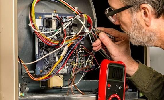
Start with the nameplate
Every HVAC appliance comes with a manufacturer’s nameplate. The nameplate will be the starting point for all of your electrical calculations. Find these values:
- Voltage (V): Typically, 120V, 208V, 240V, or 480V
- Full Load Amps (FLA): The amps the motor draws when working at full capacity
- Minimum circuit ampacity (MCA): Minimum wire size rating of the circuit
- Maximum overcurrent protection (MOCP): The maximum allowable fuse or breaker
- Locked rotor amps (LRA): The amount of current drawn by a motor during startup
By code you must use the larger FLA or the value provided by NEC Table 430.250. Use these values when calculating proper conductor size and protection devices. Never skip reading the nameplate. It tells you nearly everything you need to know.
The 125% rule for conductors
If you know one rule, know this one. Any motor load that runs continuously for three hours or more must have conductors sized at 125% of the FLA.
Formula:
MCA = FLA x 1.25
Example: your condenser calls for an FLA of 20 amps. Your MCA would be calculated like this:
20 x 1.25 = 25 amps
So now you would need to select a wire with an ampacity rating of at least 25 amps. If you’re using copper wire, Table 310.15 would put you on 10 AWG wire which is rated for 30 amps.
If you have more than one motor connected to a circuit, you must calculate the largest motor at 125%, then add every other motor at 100%
Formula:
MCA = (Largest FLA * 1.25) + (All other FLAs * 1.0)
This formula ensures you properly size wire for the combined load of all motors running simultaneously.
Size Your Overcurrent Protection
A breaker (or fuse) protects both the wiring and connected equipment. The NEC allows most HVAC compressor units to be protected at up to 175% of FLA. However, if your breaker trips during startup due to the compressor’s inrush current, you are allowed to go up to 225%.
Formula:
Max OCPD = FLA * 1.75 (or 2.25 if necessary due to in-rush current)
Example:
20 * 1.75 = 35 amps. We round up to the next standard breaker size which would be a 40 amp breaker.
NEC says you cannot exceed the MOCP value printed on the equipment nameplate. If your calculations exceed that value, you must use the lower value.
Voltage drop formula
Long wire distances cause voltage to drop before it reaches the equipment. Voltage drop impairs performance, then kills motors over time. Code requirements via the NEC says voltage drop should be no more than 3% on branch circuits. No more than 5% voltage drop overall from service panel to load.
Formula:
- VD = ( 2 * K * I * L ) / CM
- VD = Voltage drop, expressed in volts
- K = Resistance constant of conductor (12.9 for copper, 21.2 for aluminum)
- I = Current in amps
- L = One-way distance in feet
- CM = Conductor circular mils (look these up in a wire table)
Three phase circuits are a little different. Instead of starting your equation with “2”, use the square root of 3 which is 1.732.
Voltage drop comes out too high? Increase your wire size. It’s easy to fix during installation and cheaper than installing a new compressor down the road.
Load calculations for service sizing
This one is important. You need to know how many amps your system will draw before you buy a panel or pull a permit. The NEC has a whole section dedicated to HVAC load calculations. The general rule is you don’t need to add both heating and cooling loads together. Why? They’re not intending to run at the same time. NEC calls this rule non-coincidence load.
HVAC Load = Larger (Total heating VA) or (Total Cooling VA)
Express all your loads in volt-amperes (VA). Once you have that number divide by voltage to come up with the required amps.
Amps = Total VA / Voltage
Example: you have a 240 volt single phase system with an HVAC load of 9,600 VA. 9600 / 240 = 40 amps required.
Once you know your HVAC load requirements, add that to your lighting and every other calculated load. The sum of these is your total service demand.
Voltage imbalance formula
Did you know voltage imbalance can kill compressors on three phase circuits? Motors don’t like it when each phase voltage isn’t exactly the same. Small variances can shorten motor life greatly. A 2% difference is more than enough to cause problems down the road.
Formula:
% Imbalance = (Max deviation from average / Average Voltage) * 100
Using a multimeter measures the voltage of each phase. Calculate the average voltage, then determine which phase voltage is farthest from the average. Divide that phase’s voltage deviation by the average voltage. Multiply by 100.
If the % imbalance is over 2% you have work to do. Fix the imbalance before starting your equipment.
Print out a Calculations sheet for every install
This is what your professional contractors should do. Print out a new Calculations sheet for every install. Using the formulas above, write down your MCA, your OCPD size, voltage drop, load calculations, etc. Not only does this help you during inspections, but it gives anyone coming into the job later a clear idea how the equipment was properly engineered.
Do the calculations. Print them out and hang them in the panel. They aren’t much help to you or anyone else if they’re only in your head.
HVAC Installation Prevents Inspection Failure with Proper Electrical Calculations Case Study
HVAC Installation Prevents Inspection Failure with Proper Electrical Calculations Case Study
A commercial HVAC contractor was setting up a new rooftop unit for a small office renovation job. While mechanically the install was simple, prior to purchasing material electrical completed all calculations for the equipment using the manufacturer nameplate:
What was calculated: Minimum Circuit Ampacity (MCA), Maximum Overcurrent Protection (MOCP), conductors sizing using the 125% rule, voltage drop across cable run, and total HVAC service load.
By completing the calculations they found that the original design used a cable size that would cause too much voltage drop across the cable because the rooftop unit was over 180 feet from the electrical panel.
Instead of installing as designed, they upsized the conductor prior to installing.
Results:
- Electrical inspection passed on the first attempt.
- The compressor saw proper voltage at startup.
- Avoided costly retrofit after installation.
Recorded calculations were included in the project file for future service calls and warranty callbacks.
Sure the bigger cable cost more money, but saving the compressor from possible damage, avoiding the electrical inspection headache, and saving time and money over the installation lifecycle was worth the minimal cost.
HVAC Electrical Calculations FAQ
Why should I do electrical calculations for HVAC equipment?
Proper electrical calculations for HVAC equipment help ensure safe and proper operation. Correctly sizing wires and protecting equipment prevents overloaded circuits, nuisance breaker trips, excessive voltage drop, overheating conductors and electrical code violations.
Where do I find the information I need to calculate HVAC circuits?
Get the supply voltage, FLA, MCA, MOCP and Locked Rotor Amps (LRA) values from the equipment nameplate.
What is Minimum Circuit Ampacity (MCA)?
Minimum circuit ampacity (MCA) is the minimum allowable current rating of the circuit conductors that supply power to the equipment. Basically, MCA values are used to determine minimum wire size for safe installation.
What is Maximum Overcurrent Protection (MOCP)?
Maximum overcurrent protection (MOCP) is the maximum size circuit breaker or fuse that can be used to protect the equipment. Under no circumstances should the installer use a breaker larger than the manufacturer’s MOCP value.
Why do motor circuit conductors need to be sized at 125%?
Motors are considered continuous loads, which means the conductors should have a 125% rating of the motors FLA to prevent overheating and comply with electrical code.
What happens if I have too much voltage drop?
Equipment doesn’t perform as well when voltage is too low, which can lead to shortened motor and compressor life. Voltage drop is common on long cable runs and can often be resolved by installing larger conductors.
How much voltage drop is too much?
Many electricians adhere to the rule of thumb limit voltage drop to:
- 3% or less on branch circuits.
- 5% or less for combined feeder and branch circuit voltage drop.
Try to keep voltage drop within these parameters to help ensure efficient equipment operation.
Do I really need to calculate total HVAC load?
HVAC load calculations help you determine if your electrical service, panel and circuit conductors can handle the load of the HVAC equipment you want to install along with your other building loads. Calculations are required for permitting, selecting the right size equipment, and electrical code compliance.
What causes voltage imbalance?
Voltage imbalance is the result of unequal voltages between phases on a 3-phase electrical circuit. Voltage imbalance can cause higher motor operating temperatures, reduced efficiency and lower compressor life expectancy.
Should I record my electrical calculations?
Absolutely! Recording your calculations not only helps with debugging installation problems later, but also provides proof of proper electrical design prior to installing equipment. Most inspectors will appreciate the extra effort when returning for final inspection and having a calculation sheet with your project records can help with any future service calls and warranty callbacks.